Classic Spanning Tree Protocol
For the CCNA 200-301 iteration, Cisco expects exam candidates to have a grasp of the later-established Rapid Per-VLAN Spanning Tree+ (RPVST+) concept. However, before delving into an evolved topic, it's crucial to take a step back and comprehend the inter-workings of the initial, classic implementation known as the Spanning Tree Protocol, defined in IEEE Standard 802.1D.
Covers CCNA Exam v1.0 (200-301) Objectives:
2.5 Interpret basic operations of Rapid PVST+ Spanning Tree Protocol
2.5.a Root port, root bridge (primary/secondary), and other port names
2.5.b Port states (forwarding/blocking)
2.5.c PortFast
Spanning Tree is reminiscent of the better known, layer 3 IPv4 mechanism 'Time to Live,' but operates within the data link stack of the OSI model. Just as 'Time to Live' (TTL) is critical in IP routing (to prevent packets from hopping endlessly), STP serves a similar purpose by maintaining the integrity of Ethernet networks. The core implementation is straightforward: to reduce the rate of unnecessary broadcast loops amongst unused interfaces. "Loops" refer to unnecessary paths in a network topology that cause frames to circulate indefinitely. STP protects your local area network against these potential performance issues.
Bridge Protocol Data Units (BPDUs)
To actively discover connected devices, switches need to relay messages about themselves. This is done through "Bridge Protocol Data Units". Messages are input every two seconds, carrying information that allows adjacent switches to understand the current network topology. This is comparable to a steady pulse, like a heartbeat.. Any further adjustments or sudden connection loss is registered and an algorithm interprets the best path for re-design.
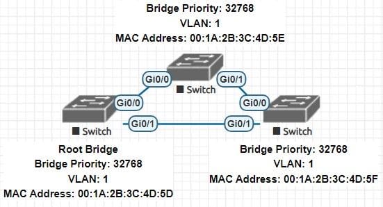
Electing the Root Bridge
The Root Bridge serves as the central reference point for determining the optimal path to reach all other switches in the network. Once layer 2 components are interconnected, a "Root Bridge" is elected amongst alike devices. The election process encompasses a form of identification, coupling all device mac addresses, applicable VLANs and "bridge priority". A "Bridge ID" compiles this information when exchanged. The switch with the lowest combination of these factors becomes the Root Bridge. If a switch receives a superior BPDU message (a message with a lower Bridge ID), the device will surrender its status and proceed to forward BPDU messages.
Selecting the Root Port:
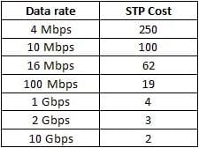
Each non-Root Bridge, is assigned one Root Port. This port connects to neighbor switches, providing the shortest path to the center of the network. It actively forwards data frames. They do so by first comparing a formed "Path Cost". Path Costs are increments assigned by interface speeds. They are the following:
The method then continues by comparing bridge and port IDs. Combined, the selection process is as shown:
- The lowest root cost.
- The lowest adjacent neighbor bridge ID.
- The lowest adjacent neighbor port ID.
Selecting the Designated/Alternate Port:
Remaining port types are responsible for message forwarding and remaining on standby for topology reorganization. Each collision domain of a switch has one "designated port" and one "alternate port". Designated ports are always actively forwarding frames. Alternate ports are implemented adjacent to designated ports for redundancy. If a designated port fails, an alternate port can swiftly transition to the forwarding state, ensuring that the network remains stable.
The selection process is similar to assigning root ports. The deciding factors are as shown:
- The interface within a collision domain with the lowest root cost.
- The interface within a collision domain with the lowest bridge ID
• Blocking State - A port does not participate in frame forwarding. It listens to BPDUs from adjacent switches to understand the network topology, but does not participate in network activity.
• Listening State - In this state, the port listens for BPDUs and prepares to transition further, but also does not forward data frames.
• Learning State - Frames now populate the MAC address table (by inspecting the source address), but again are not forwarded.
• Forwarding State - The operational state for a port. Data frames are adequately forwarded between devices.
By orchestrating the flow of data and managing redundancy, STP ensures that networks remain stable and efficient.